Posted by Julia Perez on 05 April, 2022
|Read more →
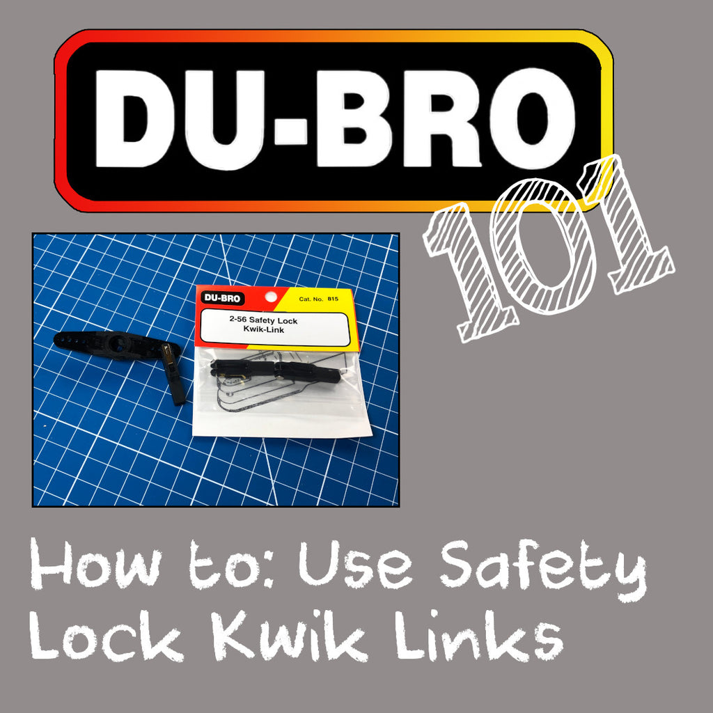
Safety lock kwik links work in much the same way you would use regular kwik links. The advantage is that they have a built-in lock to retain the link in place that makes for easy inspection and maintenance.
In this overview, the use of the link and the lock is demonstrated so you know what to look for when using them on your models.
Posted by Julia Perez on 05 April, 2022
|Read more →
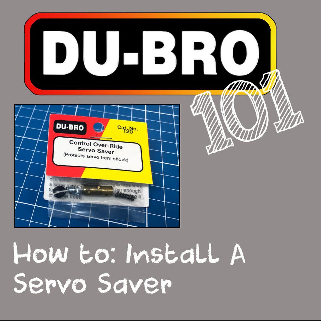
A handy kit, the Du-Bro Control Over-Ride Servo Saver, comprised of parts that you probably should have at least one of in your shop for when you need it. It’s an essential and handy fix for models.
The installation is as follows:
Insert the two screws into the two brass collets. These will act as end stops.
Determine the amount of movement you need in your application and from there also determine how many springs you should use.
Install the stack of parts as described in this video, as well as on the packaging.
Adjust centering as-needed with the collets and clip off excess push rod material to avoid binding of the push rod.
Posted by Julia Perez on 05 April, 2022
|Read more →
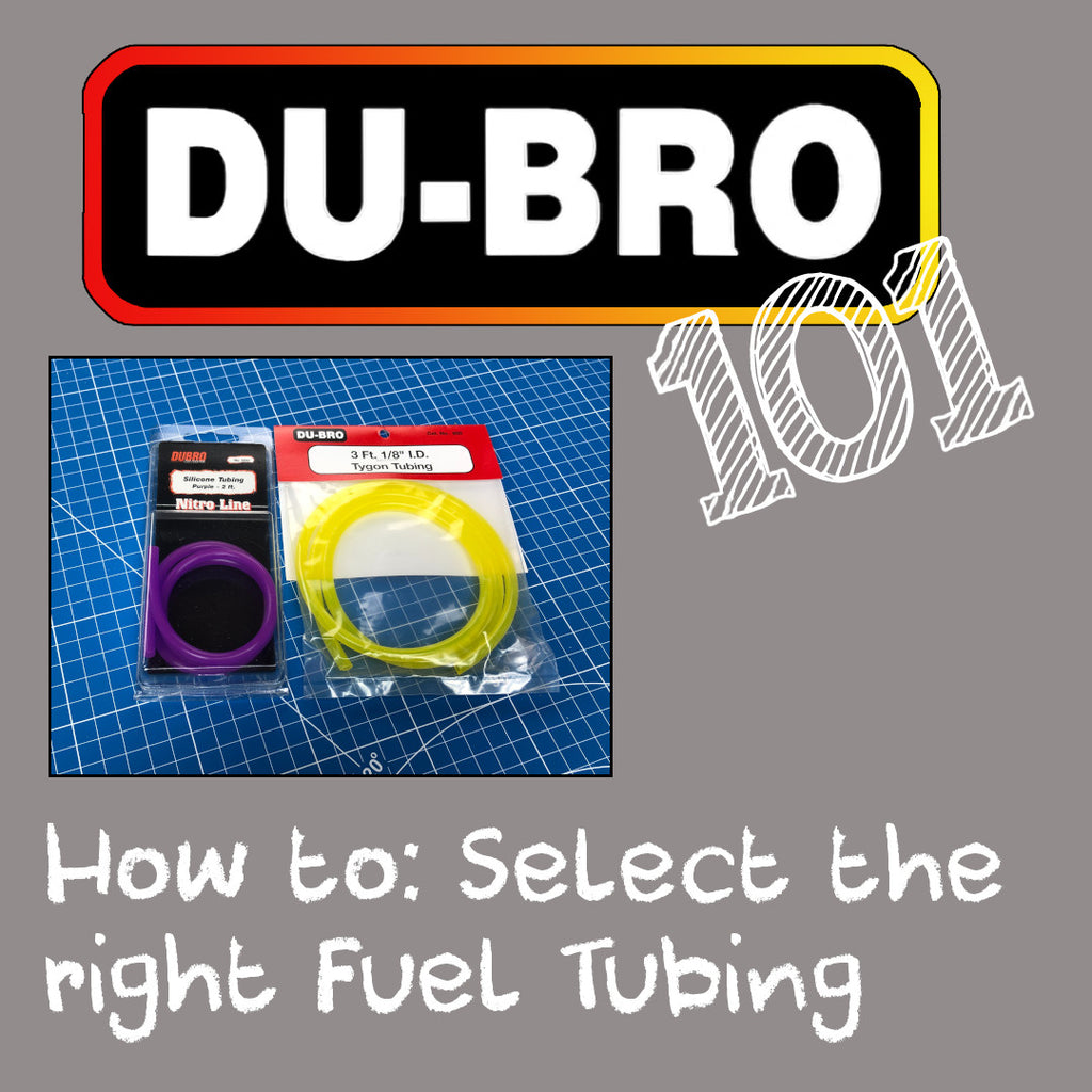
Selecting the proper tubing for your application is equally important for your model as it is for your car. Chemical compatibility is formulated into the material used for a specific fuel usage. The rules to follow are:
- Tygon for gasoline-based fuels
- The silicone tubing also comes in several fun colors.
Posted by Julia Perez on 05 April, 2022
|Read more →
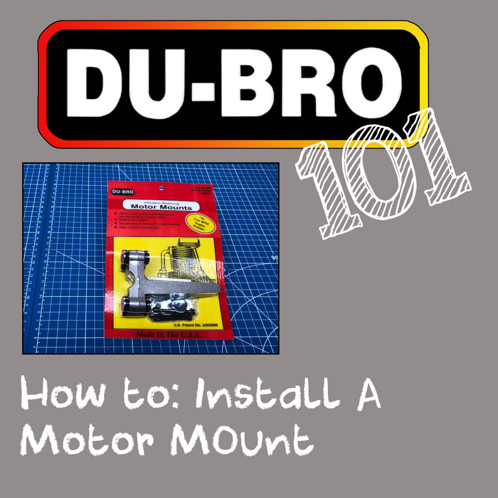
Unique in design, the Du-Bro engine mount system prevents wear and tear on your entire model by reducing vibration. A breeze to install if you take it one step at a time. The installation instructions to this critical step are outlined as follows:
• Remove the elastomer bushings from the mounts. There are 4 per side of the mount.
• Holes need to be drilled for your specific engine by using the instructions for your model to determine the distance between the firewall and the front of the prop hub on your engine. Don’t forget to account for an additional 5mm of depth for the elastomer!
• Using a small spring clamp, you can mark the hole locations for drilling.
• A clamp or vise is recommended to secure your mounts while you drill them. Also use lubricant when drilling.
• With the mounts cleaned of any metal shavings and bolted to the motor, lubricate your elastomers with castor oil or similar oil.
• Determine the orientation of the motor on your model’s firewall and measure the distance between your mounting holes for your firewall.
• Determine the center point on your firewall and use reference marks to then transfer your mount hole measurements to your firewall.
• If retrofitting, plug old holes using hardwood dowels and epoxy/CA glue.
• After drilling holes, install two blind nuts (supplied) at opposite corners on the inside of your model using another bolt (supplied) and blind nut to compress the nut into the wood.
• Install the motor mounts into your two blind nuts and then install the other two bolts and blind nuts.
Posted by Julia Perez on 30 March, 2022
|Read more →
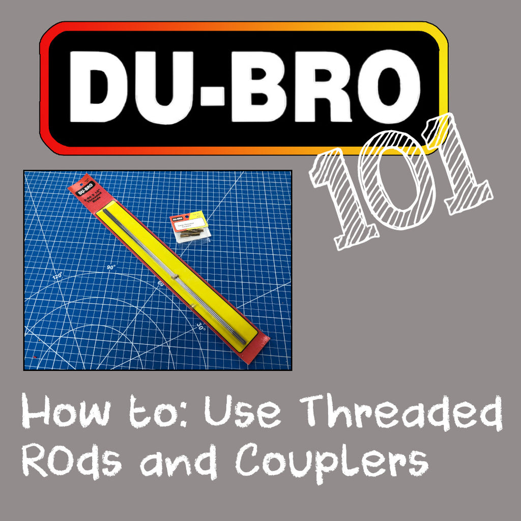
Threaded rods and threaded couplers are made for each other for a secure and robust linkage for your control surfaces. The threaded coupler has a cup that is 1cm deep that will receive your threaded rod once you cut it to the length you need.
In this video I cover some best practices with the procedure to make your own custom linkage using threaded rods and threaded couplers. The main points, with some details too, are:
Measure the length of rod needed between linkage points. I’m using Du-Bro Safety Lock Kwik-Links. I measure the length to use by intending to us threads entirely into each link.
Using a Metric ruler (remember that 1cm deep cup), mark where to cut the rod and cut it using side cutters or dykes.
Rough up the end of the rod with some old sand paper laying around just to create additional surface area for solder to grab onto. Clean this end too with rubbing alcohol or another suitable degreaser.
Dip the freshly cleaned threaded rod end into some soldering flux and insert this into the cup of the threaded coupler.
Using mechanical (not electrical) solder, create a half-circle of solder and set this on the joint of the rod and coupler using helping hands to keep the this upright for solder to flow into the cup.
Apply heat using a small butane torch or other suitable heat source for soldering only just until the solder stops boiling in the cup so that you know all the air is out and there will be no voids.
Once cooled, clean your solder joint and I recommend just a drop of ketchup to do this. The acid in it will clean up the joint very well.
Install your clevis links on each end and install to your control surface.
Posted by Brian Bychowski on 01 February, 2022
|Read more →
This video demonstrates how to use and install a DU-BRO ¼ Scale Turnbuckle. Here are some highlighted notes:
The turnbuckle has two different threaded ends that allows the turnbuckle to be used to loosen or tighten a line by twisting the center barrel section
There is a locking nut that can be tightened up against the barrel to lock the turnbuckle into position using a small screwdriver (or allen key) and needle nose pliers
Affixing each end can be done any number of ways but you can also use nylon-coated beading wire and crimps using similar techniques that were used in our pull-pull line video
Turnbuckles are a beautiful scale addition to your model that will can also be used for functional strength and reinforcement
Posted by Brian Bychowski on 28 September, 2021
|Read more →
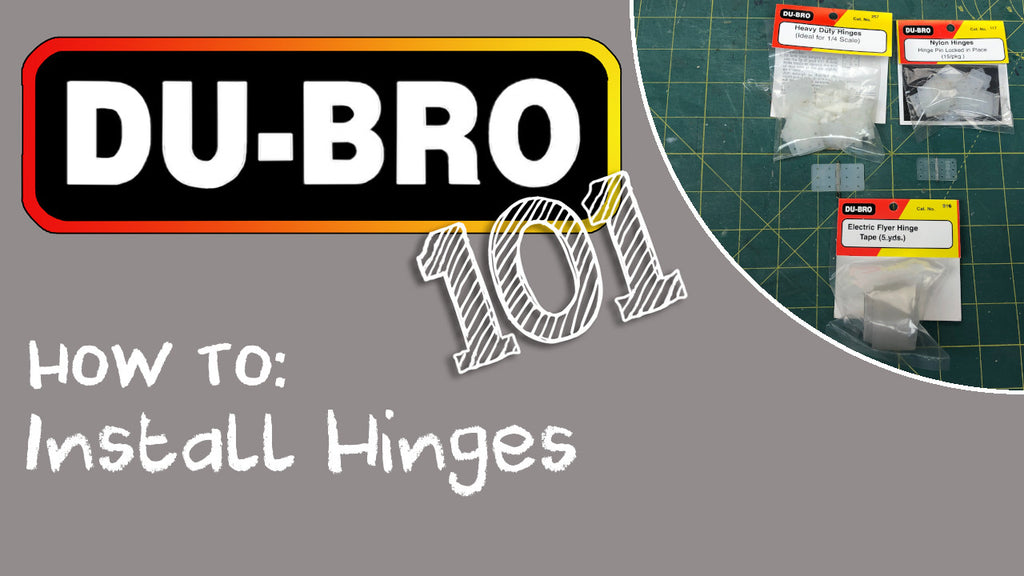
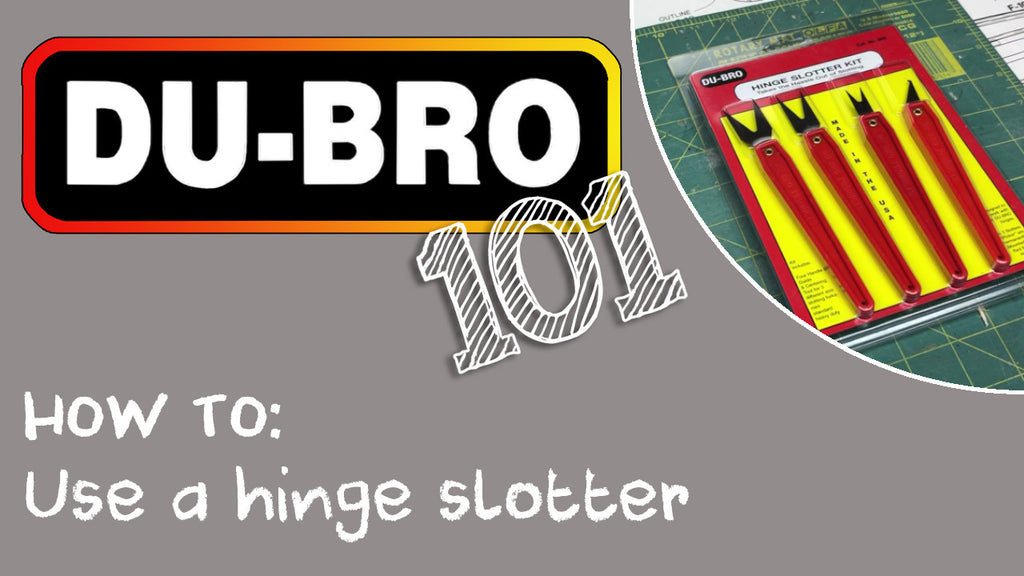
This video shows the proper way to install DU-BRO nylon hinges and Electric Flyer Hinge Tape on the control surfaces of an RC airplane model. Some key information about the DU-BRO hinge slotter:
There are two styles you can order: No handles = Cat. No. 216 and With handles: Cat. No. 660
Small parts from the kit can be easily stored in an old servo box.
The center piece of the parallelogram tool is interchangeable for different slot widths and the hole center tool
The hole center tool can be used to make holes for aileron torque rods as well as holes for CA application
Fork tools are inserted using a rocking motion until the slot is created.
For harder woods, mark the edges of the slot to be made and drill holes. The hook tool is then used to make the slot.
Be mindful of your fingers as injuries can happen with these fairly sharp instruments.
Store everything clean so they are ready to use again in the future.
Posted by Brian Bychowski on 16 September, 2021
|Read more →
In this video we show you the benefits and proper use of the DU-BRO Hinge Slotter Tool (Cat. No 660 and 216). This innovative tool will help you create the perfect slots for the hinges on your RC model aircraft.